تخلیه سریع شارژ باطری
یکی از مشکلاتی که برای گوشی ها به وجود می آید خالی شدن شارژ گوشی است.
. با یک باطری وشارژر اصلی تخلیه شارژ بررسی شود
دانلود X plore File Manager android
- نمایش شاخه ای پوشه ها با دو صفحه نمایش (انتقال آسان میان پنل ها)
- پشتیبانی از سرویس های ابری Google Drive™, Dropbox, SugarSync, Box.net, SkyDrive
- افزودن پوشه ها به علاقه مندی ها (Favorite)
- نمایشگر داخلی برای فایلهای متن، عکس، ویدئو، صوت
- نمایشگر Hex
- نمایش سریع تصاویر با قابلیت زوم و مرور تصاویر قبلی و بعدی
- نمایش تصاویر بندانگشتی (Thumbnails) برای انواع فایلها
- قابلیت انتخاب چندگانه به صورت کاملا آسان (بدون نیاز به هیچ گزینه ای)
- نمایش فایلهای APK همانند فایلهای ZIP
- اشتراک گذاری اطلاعات توسط بلوتوث، ایمیل، و دیگر نرم افزارهای پشتیبانی شده توسط گوشی
- شخصی سازی دکمه ها و میانبرها
- جستجو گر داخلی
- FTP داخلی
- LAN داخلی (دسترسی به پوشه های به اشتراک گذاشته شده کامپیوتر از طریق موبایل)
- دسترسی به فایلهای سیستمی (در صورت روت بودن گوشی)
- و بسیاری از امکانات دیگر.....
دانلود Premium Scanner: PDF Doc Scan 26.1.0 - اسکنر هوشمند اسناد اندروید !

در بین تمامی نرم افزار های اندرویدی اسکنر ها را شاید بتوان جزو پر طرفدار ترین ها دانست که کمک می کند در هزینه های خود صرفه جویی کرده و اسناد اسکن شده شخصی خود را ایجاد کنید. Premium Scanner: PDF Doc Scan عنوان یک اپلیکیشن اسکنر هوشمند می باشد که توسط LineApps برای اندروید منتشر شده است
برخی از امکانات و قابلیت های برنامه Premium Scanner: PDF Doc Scan اندروید :
اسکن و ذخیره فایل ها تنها با یک شات
دسترسی به فیلتر هایی متنوع برای ایجاد تغییرات در اسناد
فعال و یا غیر فعال کردن فلش در هنگام ثبت تصاویر
شناسایی لبه اسناد به صورت خودکار با امکان ایجاد تغییرات به صورت دستی
مشاهده پیش نمایشی از اسناد اسکن شده
اضافه کردن اسناد اسکن شده در سرور های ابری
امکان ذخیره اسناد در دو فرمت pdf و jpeg
تغییرات نسخه v26.1.0 :
لینک دانلود فایل در قسمت پیوندهای وبلاگ
DIY Breadboard Power Supply Circuit on PCB
یک منبع تغذیه ابزار اغلب مورد استفاده توسط بسیاری از مهندسان در مرحله توسعه است. من شخصا هنگام استفاده از طرح های مدار خود در Breadboard یا استفاده از یک ماژول ساده از آن استفاده می کنم. اکثر مدارهای دیجیتال یا مدارهای تعبیه شده دارای یک ولتاژ عملیاتی استاندارد 5 ولت یا 3 ولت هستند، بنابراین تصمیم گرفتم یک منبع تغذیه را تولید کنم که می تواند 5 ولت / 3.3 ولت بر روی راننده های نوت بوک را تامین کند و به راحتی بر روی صفحه نویسی قرار بگیرد.
منبع تغذیه کامل بر روی PCB با استفاده از EasyEDA طراحی شده است. مدار از 7805 برای تامین 5 ولت و LM317 برای تامین 3.3V با حداکثر امتیاز فعلی 1.5A استفاده می کند که به اندازه کافی منبع برای مدارهای IC و Microcontroller دیجیتال است. پس بیایید شروع کنیم ....
مواد مورد نیاز
تنظیم کننده ولتاژ متغیر LM317
7805
DC Barrel Jack
مقاومت 330 و 560 اهم
0.1 و 1uF خازن
نور چراغ
برگستیک مرد
PCB (از JLCPCB)
مدار
مدار مدار کامل برای این پروژه تغذیه Breadboard در زیر نشان داده شده است. مدار با استفاده از Easy EDA ایجاد شد.
مادربرد Universal Smart LED TV با یک خازن کوچک ذخیره می شود
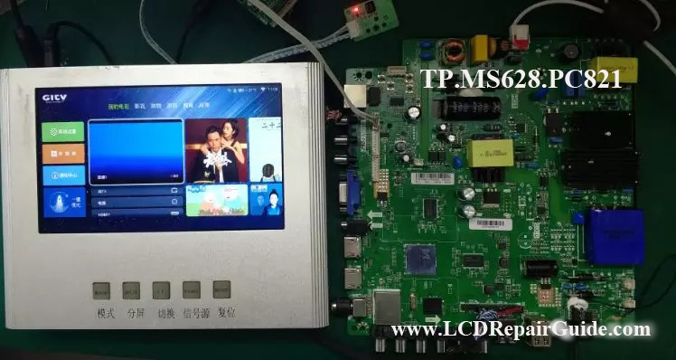
Today, a TV repairer sent a malfunction LED/LCD TV Mainboard asked for help. He said this TV Mainboard some time can work fine but some time not. When the TV mainboard is not working, try to read their “Start-up Log” (for more details, please read my V5.0-OLED/LED TV Repair Tips ebook) through RT809F programmer, but nothing at all. If shorted the 5V_STB & 5V_M, the Start-up Log can printing/show normal information. Disconnect the 5V_STB & 5V_M, press the power on button, the TV Mainboard can operate and working fine.
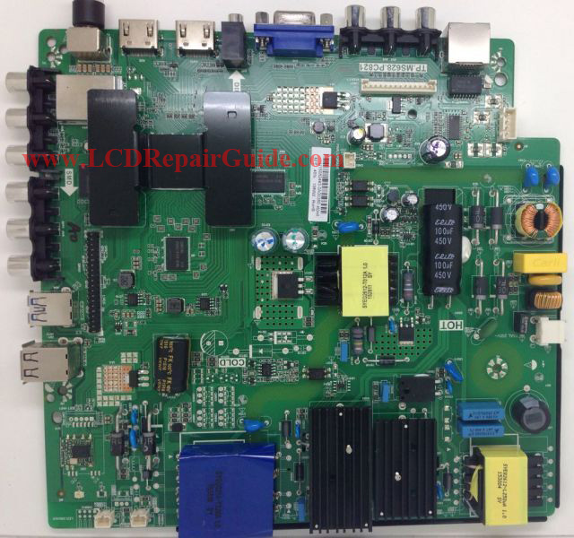
After testing this TV mainboard, the TV Mainboard symptom is like he said exactly same. The TV mainboard when supplied voltage, their 5V_M no any voltage appear at all. Normally it will appear 5V_M a moment then off when TV is in Standby Mode.
Before we analyze the failure of the Mainboard, let’s look at the power start-up sequence of the whole TV mainboard. The first stage of TV Mainboard starting up requires the CPU to be ready. For the CPU to be ready, the first working condition is their power supply supplied. For example power supply like standby voltage, CPU kernel voltage and digital circuit power supply.
When the TV Mainboard is powered on, in fact, all the power supply is not been controlled. Which means the CPU gets all the power supply at the moment of power on, their reset circuit and clock circuit are work at the same time. After meeting all the condition of the CPU, the CPU begins to read the BootLoader program/firmware & transfer the control right, and then it starts to initialize the hardware device. If all normal, the “Start-up Log” or print information will appear on RT809F program.
After the hardware device initialization is completed, it returns to the standby mode and the control circuit that the output of 5V_M is cut off and waiting for the boot command (press power on button from TV or Remote Control).
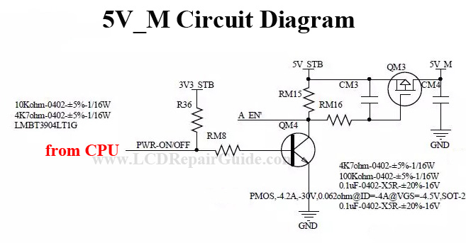
From the malfunction of the TV Mainboard, their 5V_M is always be in no output state. So the power supply of CPU is not enough at the moment of power supply supplied and it will not or can’t start-up the TV mainboard.
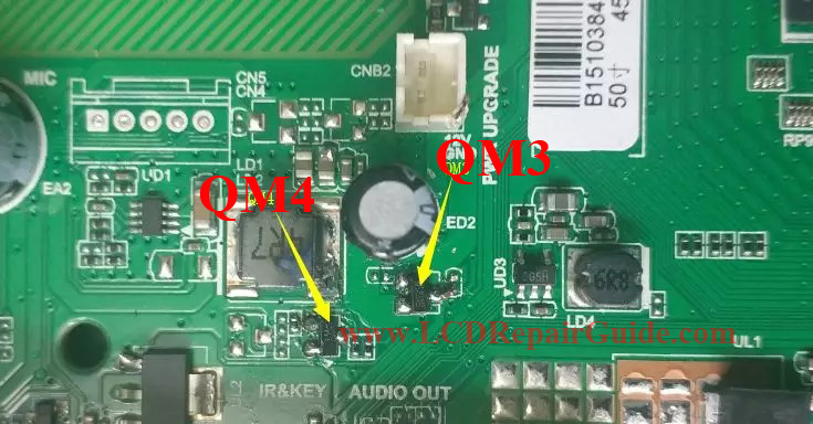
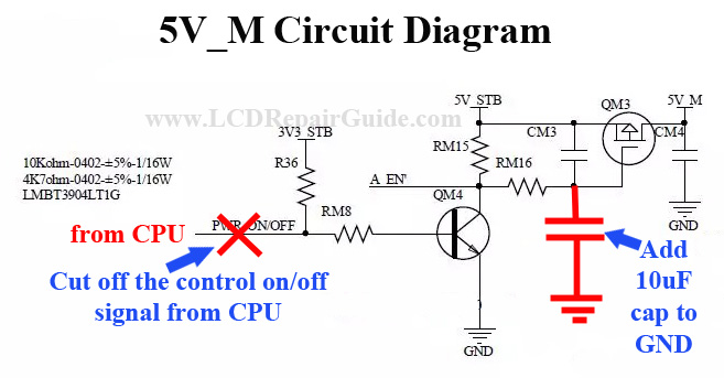
So, first of all, we need to check their control circuit state, 5V_M circuit. Measured the QM3 pin-G (Gate pin) is 5.1V and QM4 pin-B (Base pin) is 0.3V. Check QM3 & QM4 transistor in diode range, both are normal. So confirm that the 5V_M circuit is in closed state.

From the above circuit diagram, we can see that the on/off signal is from main chip (CPU). Measure the left side of RM8 resistor is about 0.23V. Try to cut off the printed circuit line (on/off control signal) from main chip. After that, their 5V_m voltage output is normal now. The conclusion is the main chip (CPU) damaged!
For this TV Mainboard, if just because of this problem to replace whole mainboard, it is not cost-effective and not worth to do that. As mentioned earlier, as long as this mainboard 5V_STB and 5V_M shorted a while then released it, the TV Mainboard can working perfectly. That’s mean the 5V_M need some voltage output a moment only, then this TV Mainboard can normal operate. What we want is that there is output of 5V_M when it is energized. So modify the 5V_M circuit to add a small SMD capacitor 10uF to QM3 pin-G (Gate pin) to ground (GND), like the photo below:
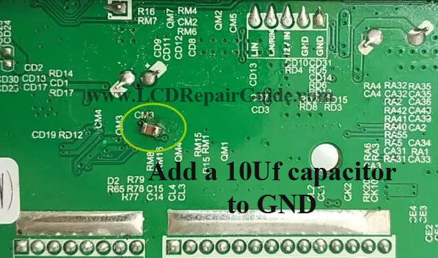
After added a small smd capacitor on the 5V_M circuit, supplied the voltage to Mainboard, press power on button, it can start-up and working properly. Press again power button, it can shutdown normal. The TV Mainboard after modify, everything is normal now. So the TP.MS628.PC821 Universal LED/LCD TV Mainboard is modifying successfully!
